Tuesday, May 26, 2015

RPi Test #5: Separation of Concerns

In the previous example, you may have noticed the beginning of "diagram clutter", where the I/O interface blocks were taking up significantly more space than the actual program logic. This problem can become severe with more complicated logic and a greater amount of I/O, such that it can become extremely difficult to even figure out what the logic is supposed to be doing.
As shown in the current example (GPIO_TEST5), we can solve this problem by applying the principle of Separation of Concerns:
  • First, as shown below, we move all the I/O interface blocks into one or more Resources separate from the program logic (here the resource is named IO for obvious reasons).
  • Then we add Local Multicast blocks to transmit inputs to and receive outputs from other Resources.
  • The Tagged Data design pattern support in the FBDK helps to keep the use of Local Multicast channels consistent among Resources.
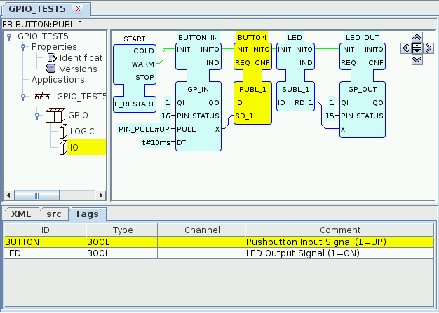
Now we add Local Multicast blocks to the LOGIC resource to receive data from inputs and transmit the results of the control logic to outputs. Notice the reduction of diagram clutter:
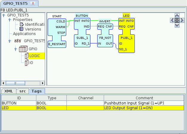
In the next example, we'll take advantage of this reduced clutter to make room for more complicated control logic.

Monday, May 25, 2015

RPi GPIO Test #4: Signal Inversion

In the previous example, a pushbutton was "soft wired" to an LED in such a way that the LED was ON when the pushbutton was up, and OFF when the pushbutton was down. This is the reverse of what you would usually expect, so in the present system configuration (GPIO_TEST4.sys), the signal is inverted using an instance of the FB_NOT function block type so that the LED is ON when the pushbutton is down.

RPi GPIO Test #3 : Soft Wiring

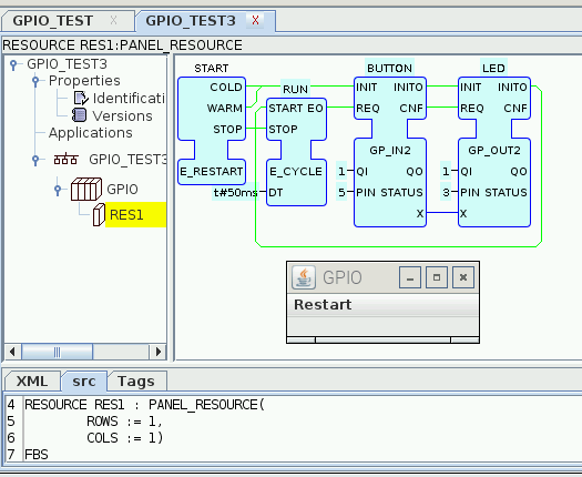
In this system configuration (GPIO_TEST3), the GPIO "loopback" connection of the previous example is replaced with connections to real devices, which replace the Graphical User Interface (GUI) elements:
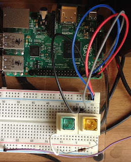
  • Pin 3 is configured as an output connected to an LED (the yellow button) in series with a 100 Ohm resistor to ground.
  • Pin 5 is configured as an input with an internal pull-up resistor, connected to a normally open pushbutton (the green button) to ground.
  • The value of the pushbutton input (BUTTON.X) is passed to the LED output (LED.X) via the graphical connection, and the LED block is notified of the current pushbutton status by the BUTTON.CNF => LED.REQ event connection.
As a result of these "software connections", the state of the LED reflects that of the pushbutton:
  • When the button is up (open), the state of pin 5 is HIGH due to the internal pullup resistor on the input pin, and this is passed to the LED on pin 3 as an ON condition, as shown in the picture on the left below.
  • When the button is down (closed), it pulls pin 5 LOW and this is passed to the LED on pin 3 as an OFF condition, as shown in the picture on the right below (the green button is held down with transparent tape in order to take the picture).

Wednesday, May 20, 2015

RPi GPIO Test #2: Loopback Testing

In this system configuration (GPIO_TEST), the Raspberry Pi GPIO configuration and loopback connection are identical to those of the previous example, with the addition of HMI elements such that the operation is as follows:
  • Clicking on the OUTPUT check box causes the OUTPUT.OUT value to flip; this value is passed to the PIN3.X input.
  • An event is passed from OUTPUT.IND to PIN3.REQ; this causes the flipped value at PIN3.X to be written to pin 3 of the Raspberry Pi 2 GPIO header.
  • The output state is passed electrically from pin 3 to pin 5 of the GPIO header.
  • An event is passed from PIN3.CNF to PIN5.REQ, which causes the value of the input at pin 5 of the header to appear at PIN5.X, which is passed to INPUT.IN.
  • An event is passed from PIN5.CNF to INPUT.REQ, which causes the INPUT display to be updated with the new value of PIN5.IN.

RPi GPIO Test #1: Service Interfaces

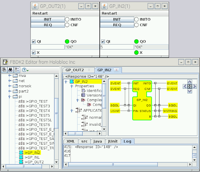
Here's a shot of a test of the first two General Purpose I/O Service Interface Function Blocks (GPIO SIFBs) for the Raspberry Pi 2:
  • Pin 3 of the Raspberry Pi 2 GPIO header is configured as an output using an instance of the GP_OUT2 type.
  • Pin 5 is configured as an input using an instance of the GP_IN2 type.
  • The output on pin 3 is looped back to the input on pin 5 for testing.
  • The value at the X input (0=LOW, 1=HIGH) of the GP_OUT instance is written to pin 3 when the REQ input is triggered.
  • The value at pin 3 is conducted electrically to pin 5.
  • The value at pin 5 can be read at the X output of the GP_IN2 instance by triggering its REQ input.
  • For more information, see the following documentation: GP_IN, GP_OUT, PIN_PULL.

Saturday, May 9, 2015

RPi Testbed

Here's a shot of the testbed I'm putting together using the Pi Dish from Adafruit. So far I'm just checking out some 35-year-old LED-illuminated push buttons I had lying around from the old Strider Systems days. Next step - develop some Service Interface Function Block (SIFB) wrappers around the built-in file system access to GPIO.